


















- Tips on machining 2018/05/25 UP
-
Tips on Machining Vol. 19
Tapping trouble and solutions
Part 2 (Thread defects)

- Tag
-
- Milling
Many people are concerned about thread defects when tapping, such as thread tearing or seizing. In fact, tearing and seizing are the most common thread defects that occur when tapping, besides breakage or thread accuracy defects. In this article, we cover the causes and solutions of thread defects.
Three typical examples of thread defects are thread stripping, thread thinning, and thread tearing. Let us take a look at the solutions for each.
(1) Thread stripping
One cause of thread stripping is when the tap and thread interfere with one another when removing the tap from the workpiece. Once the tap has reached the specified depth, it can be removed from the workpiece by rotating in the opposite direction. However, the tap must follow the same exact path when going in (machining) and going out (returning). If the out path differs even slightly from the in path, the tap and thread will interfere with each other. This can cause thread stripping.
It seems as though this would not be an issue with a rigid tap, since the rotation of the spindle and the feed motion are synchronized perfectly. However, the mechanical motion is actually slightly delayed relative to the commands of the control system. When the mechanical motion is delayed relative to the commands of the control system, it is referred to as a "synchronization error." It is this synchronization error that causes the in and out paths of the tap to differ, resulting in thread stripping. Synchronization errors are more likely when there are gears and belts in the drive system.
Synchronization errors are also often caused by errors due to cutting resistance. When machining, resistance increases along the in path due to cutting, while resistance decreases along the out path because there is no cutting in that direction. This difference in resistance can cause synchronization errors.
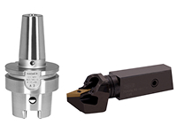
One effective way of eliminating the impact of synchronization errors is to use a tap holder equipped with a shock-absorbing structure and expansion/contraction functionality. When returning the tap, this type of holder will absorb any excessive force applied to the tap in the axis direction to suppress thread stripping. The holder will also absorb cutting resistance if the tap bites into chips, which can prevent breakage. Synchronization errors can also be reduced by modifying a parameter (the time constant). However, this requires caution, as modifying a parameter will affect other types of machining in addition to tapping.

A tap holder with expansion/contraction functionality.
*Material provided by OSG CORPORATION
(2) Thread thinning
One cause of thread thinning is the propulsive force acting on the tap. When tapping, propulsive force is generated by the thread of the tap and the ejection of chips. However, when using a spiral tap, chips are normally ejected in the direction opposite the feeding direction, and the tap will attempt to advance beyond the feed command value. In contrast, a point tap will eject chips in the feeding direction and will tend to lag behind the feed command value.
A tap will therefore tend to either advance ahead of or lag behind the feed command value when machining and will cut away material that was meant to be a thread, causing thread thinning. Errors in mechanical motion and tap motion are similar in concept to synchronization errors, and thread thinning can be suppressed by using a tap holder equipped with a shock-absorbing structure and expansion/contraction functionality.
(3) Thread tearing
The two major causes of thread tearing are inappropriate cutting speeds and galling.
A: Inappropriate cutting speed
The cutting speed is set according to the material of the workpiece. However, setting too high a cutting speed can cause tearing. If using a soft material such as low-carbon steel, a fast cutting speed will cause a phenomenon called chafing, and the tap will rub against the material and cause tearing. This can be resolved by setting the proper speed. For example, if tearing occurs when machining SS400 at around 8 m/min, the speed should be reduced to 3 m/min.
When using rigid tapping (synchronized tapping), machining is sometimes performed at a cutting speed of 20 m/min or higher even with steel material. However, a high speed can cause chafing and tearing, so it is a good idea to try reducing the cutting speed even in such cases.

Female thread surface machined at reduced cutting speed
Too low a cutting speed can also cause tearing. A slow cutting speed can reduce the cutting ability of a tap. If tearing occurs, the key point is to supplement the cutting ability of the tap, such as by using tapping paste containing plenty of extreme-pressure additive, coolant containing chlorine, or coolant that is roughly ten times thicker than normal.
B: Galling
(1) Work material is mild steel
When the work material is mild steel (such as low-carbon steel), the cutting point temperature will increase if the cutting speed is high. This will soften the material, which makes it easier for part of the work material to become adhered to the edge and cause galling.
Two effective means of reducing frictional resistance is to apply tap paste (which makes the cutting fluid water-insoluble), or momentarily apply oil shot type oil-based cutting fluid to the tap. In other words, it is important to select the proper coating based on the work material.

(2) Work material is hard steel
When the work material is hard steel (such as stainless steel), machining will cause work hardening and the surface will become harder. In order to minimize work hardening, frictional resistance must be reduced. There are two ways of reducing friction. First is to use a different cutting fluid (as with mild steel). Second is to drill tiny holes in the surface of the tool to help cutting fluid more easily accumulate.
As with mild steel, machining hard steel material can cause galling. However, the type of galling that occurs with hard steel material differs from galling resulting from tool wear. In this case, nitride treatment can be used to increase the hardness of the tool surface and suppress tool wear, preventing galling and extending tool life.
(3) Tapered pipe threads
Tapered pipe threads are machined by passing through the same thread many times, resulting in thinner chips compared with parallel threads. This can cause galling if the edge slips. Two effective means of reducing frictional resistance are applying cutting fluid and making use of tool surface treatment.
An effective means of preventing galling is to use through spindle coolant sprayed directly near the cutting point to increase lubrication. For blind holes, an effective solution is to spray from the center of the tool. For through holes, it should be sprayed from around the complete thread on the outer circumference of the tool.
This concludes our article on thread defects and solutions. If you have any concerns or questions about tapping even unrelated to thread defects, please feel free to contact a DMG MORI engineer. One of our experienced engineers will be happy to work with you on a solution.