









Grinding Centers

Vertical Multi-Process Grinding Machines

Small-type Vertical Grinding Machines

Deep-Hole Grinding Machines

Internal Grinding Machines

Thread Grinding Machines

CLOSE

Tips on machining

  • Tips on machining 2017/12/08 UP
  • Print

Tips on machining vol.15
How to utilize normal and reverse rotations on a turning center

Share
Tag
  • Turning Centers
  • Turning

Previously, when machining was performed on a turret-type turning center, a right-hand cutting tool was attached to the machine with its rake face facing down, and the workpiece (spindle) was rotated in the normal direction. The reason for doing so was that the face-down rake face allows cutting chips to fall by gravity, which makes chip disposal easy. However, machining trends have changed over the years; faster machining is demanded for the sake of greater productivity, and chip discharge speed has also increased in line with that. As a result, a problem that flying chips can damage the internal sheet metal parts has emerged.
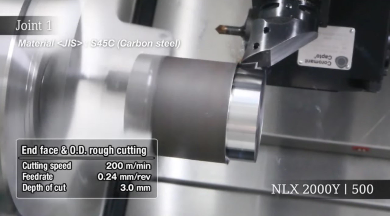
Machining with a right-hand cutting tool

Then, a new machining method, in which a left-hand cutting tool is attached to a machine with its rake face facing up and the workpiece is rotated in the reverse direction, has been widely used in recent years. The reason for doing so is that the face-up rake face allows chips to scatter upward into the air to prevent damage to the internal sheet metals and makes insert changes and tool tip (cutting phenomenon) checks easier.
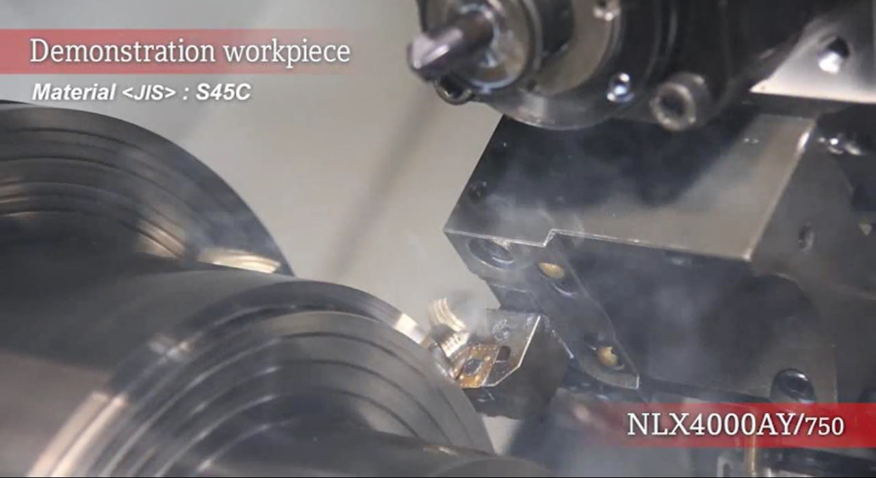
Machining with a left-hand cutting tool

The rotation direction of a workpiece mounted on a turning center has changed from normal to reverse in the historical context as mentioned above. Today, one of the most effective machining techniques is to change the spindle rotation direction according to the purpose of machining.

For example,if a right-hand cutting tool is attached to a slant-type turning center with its rake face facing down and the workpiece is rotated in the normal direction, cutting resistance (main component force) acts in the direction in which the turret is pulled up (or the direction away from the guide). This could cause the degradation in machining accuracy in grooving or heavy-duty cutting which involves a large depth of cut and cutting resistance. In particular, machining on a turning center with a slant angle of 60 deg. or greater is more likely to generate chatter due to low rigidity that is caused by the nearly-vertical Z-axis slideways.

Fig.5 Bed of the slant-type turning center

This means that you can achieve stable, chatterless heavy-duty cutting on a slant-type turning center by attaching a left-hand cutting tool to the machine with its rake face facing up and rotating the workpiece in the reverse direction, as cutting resistance (main component force) acts in the direction in which the turret is pushed down (or the direction with higher rigidity). (Fig. 6)

Fig. 6 The image of a turret pushed down by the main component force

The reverse rotation of a workpiece also brings some advantages. For instance, it can make left-hand tools unnecessary if a workpiece is cut from the chuck side toward the tailstock with a right-hand tool. This allows you to use the same right-hand tool for a turning center and a general-purpose lathe, or to machine the outside diameter using a right-hand I.D. cutting tool. The effective utilization of both rotation directions makes it possible not only to suppress chatter and improve machining accuracy, but also to reduce the number of tools.

Fig. 7 Simultaneous machining with upper and lower turrets
(With the lower turret, machining is conducted from the chuck side to the tailstock with a right-hand tool.)

Here are basic principles in the effective use of normal/reverse rotations on a turning center.

■Normal rotation

・O.D. cutting tool is mounted with its rake face facing down for better chip disposal
・Machining of right threads

■Reverse rotation

・O.D. cutting tool is mounted with its rake face facing up for better visibility
・Enable cutting resistance to act in the direction in which the turret is pressed against the bed for minimizing chatter
・Attach a right-hand grooving tool to the end face holder
・Cut a workpiece from the chuck side to the tailstock with a right-hand tool
・Machining of left threads

■Normal/reverse rotation

・Normal rotation followed by reverse rotation for deburring
・Perform both I.D. and O.D. machining with either an I.D. or O.D. cutting tool.
・If you bought a wrong hand tool

The machining techniques introduced above are only a few of the examples. DMG MORI provides various solutions for your production improvements. With only a little ingenuity, you can achieve higher machining accuracy, production efficiency and shop floor improvements including standardization of tools. If you have questions or concerns about machining on a turning center, please feel free to contact us.

The bookmark function is a service restricted to members.
To use it, you must register as a member and log in.