Grinding Centers

Vertical Multi-Process Grinding Machines

Small-type Vertical Grinding Machines

Deep-Hole Grinding Machines

Internal Grinding Machines

Thread Grinding Machines

CLOSE

Tips on machining

  • Tips on machining 2018/03/23 UP
  • Print

Tips on machining vol.17
Machining technique learned from hexahedral cutting

Share
Tag
  • Personnel training
  • Milling

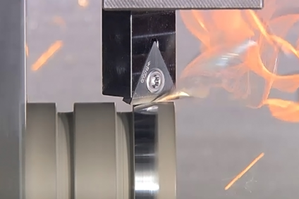
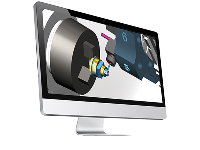
Horizontal, orthogonal and parallel are the fundamental elements to represent shape accuracy. A hexahedron is a shape that contains all of these three. So, a hexahedron is always used as basic assignments in the practical training of milling and serves as a yardstick to measure trainees’ milling skills; an accurately machined hexahedron can prove that the trainee’s milling skills have reached a certain level. In this article, we introduce practical know-how and expert knowledge to pursue machining accuracy, taking hexahedral cutting as an example.

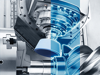
Fig. 1 Hexahedron cutting

To conduct milling, a vise needs to be attached on the table. In fact, the pursuit of machining accuracy starts with this operation. The vise serves not only as a fixture to secure a workpiece but also as a base to achieve high machining accuracy. When attaching a vise on the table, we have to check, with our own eyes, the parallelism (in the X-axis direction) and squareness (in the Z-axis direction) of the vise mouthpiece as well as the horizontality (in the Y-axis direction) of the slideways with which a workpiece comes into contact, to make sure the vise has been attached horizontally and at a right angle. And this is something we must do ourselves.

Fig. 2 Relationship between vise and axes

When a plane surface is machined with a face mill cutter, cutting in general is performed in the X-axis direction, and do you know why? (In other words, why machining is not performed in the Y-axis direction?) A machining center employs a table that moves in the X- and Y-axis directions, and a saddle is mounted on the Y-axis to support the table, while nothing was mounted on the table. This means the X-axis can move more lightly and offer better dynamic performance than the Y-axis. That’s why milling is conducted in the X-axis direction. It also helps maintain a clean work environment as there is no chip accumulation on the operator side.

To machine a plane surface with multiple tool paths, the following three paths are conceivable: (1) reciprocating cutting, (2) one-way cutting, and (3) U-shape cutting. (See Fig. 3)

Fig. 3 Three tool paths for plane surface machining

(1) Reciprocating cutting
The advantage of reciprocating cutting is that a tool path is short, and the disadvantage is that a surface is likely to be uneven at the seams of a tool path. The direction of cutting resistance changes in accordance with the change in cutting direction, which induces a change in the spindle tilting direction and thus generates uneven surfaces. For these reasons, reciprocating cutting is suitable for roughing in which high accuracy is not required.

(2) One-way cutting
One-way cutting is suited to the finishing process thanks to its constant machining direction, which is less likely to generate uneven surfaces at tool path seams. It also has a disadvantage of a longer tool path.

(3) U-shape cutting
U-shape cutting can control places where large burrs are formed because there is only one exit for a face mill cutter to come out from the workpiece, which is the advantage of U-shape cutting. However, just like reciprocating cutting, U-shape cutting involves changes in the machining direction, so it is not suitable for finishing, a cutting process requiring high accuracy.

The important points for hexahedral cutting are outlined above. Every operation, including one that often taken for granted in our regular work inevitably has logic, such as “Where is the reference face?”, “In which direction does cutting resistance apply?” or “In which direction do cutting chips fly?” In order to further improve our machining skills, it is important for us to pursue higher machining accuracy, bearing such logic in mind. It is no exaggeration to say that high machining accuracy that can be achieved by operators’ steady efforts demonstrates their tireless efforts and strong confidence towards even higher quality and productivity.

With more and more machining centers and turning centers being numerically controlled, the range of human tasks has been narrowed, and the focus has shifted to setups, cutting conditions and tool path settings. Moreover, under the current circumstances where operators cannot view the machining point with their own eyes, they are required to increase their ability to imagine machining phenomena.

Table 1 shows a practical cutting procedure for a hexahedral workpiece. If you have any problems or questions about machining methods, procedures or conditions, please feel free to contact us. DMG MORI will support your machining process innovation by our broad experience and expertise.

Table 1. Hexahedral cutting procedure

Process 1: machining of 1st face

  • Put the 4th face, which is large and forms a relatively stable right angle, to the mouthpiece to machine the 1st face.
  • Since this is the first face to be machined, chucking should be done in such a way that the 4th face is firmly put against the mouthpiece.
  • Do not hit the workpiece from above with a hammer. Otherwise, the 3rd face is likely to fit into the shape of the sliding part, causing less contact between the 4th face and the mouthpiece.
  • Insert a round bar between the 2nd face and the mouthpiece on the push side.→The 2nd face makes line contact with the mouthpiece on the push side as they are not parallel to each other, which allows only the 4th face to be pushed against the workpiece.
  • Machining should be conducted under moderate cutting conditions because the clamping force is not enough at the 4th face, the bottom contact surface of 3rd face, and the 2nd face on the push side.
  • Machining should be done to such an extent that the rough surface of the uncut material is removed.
  • Burrs generated during cutting need to be removed so that they do not protrude from the outer periphery.

[Key Points]

  • Machining is conducted under the unstable chucking status, so cutting should be as light as possible to prevent distortion/deformation and reduce impacts on subsequent processes.
  • The 4th face that has been put against the mouthpiece will be the first reference surface. Put the 4th face firmly against the mouthpiece. Do not use a hammer, and do not press the push side forcibly.

Process 2: machining of 2nd face

  • Place the 4th face, a reference surface in Process 1 at the bottom. Machine the 2nd face, with the machined 1st face being put against the mouthpiece.
  • The 4th face, a reference surface in Process 1, is placed at the bottom.
  • Do not hit with a hammer. Insert a round or square bar between the push side and the 3rd face.
  • Burrs generated during cutting need to be removed so that they do not protrude from the outer periphery.

[Key Points]

  • The 4th face, which was pressed against the mouthpiece in Process 1, is used as a reference bottom.
  • Because chucking is still unstable, cutting should be performed lightly.

Process 3: machining of 4th face

  • Now that the machining of the 2nd face has been completed, machine the 4th face with the 2nd face used as the reference surface.
  • Hit the 4th face to make sure the two machined faces have been in close contact with the bottom.
  • A round bar should remain inserted, as the 3rd face on the push side has not yet been machined and thus lacks stability.
  • The widths of the 2nd and 4th faces should be machined as specified in the drawing.
  • Measure the width (thickness) at four corners. If fluctuations are observed in the measured values, there may be foreign matter or burrs remaining at the bottom.

[Key Points]

  • The 2nd face has been machined. Make sure that this face should come into close contact with the vise.
  • Machining should be conducted in accordance with the dimensions of the 2nd and 4th faces given in the drawing.
  • Completely remove burrs and foreign matter when bringing the finished surface into contact with the bottom surface.

Process 4: machining of 3rd face

  • Place the 1st face which was machined in Process 1 at the bottom, and put the 2nd face which was machined in Process 2 to the mouthpiece.
  • Now that stable chucking is possible and the 4th face on the push side has been machined, hold the workpiece directly.
  • If the 5th and 6th faces, which will become the sides of the workpiece, can be machined with an end mill, either of the two shall be machined.
  • Measure the width (thickness) at four corners, and if fluctuations are observed in the measured values, there may be foreign matter or burrs remaining at the bottom.

[Key Points]

  • Make sure the machined face has come into close contact with the vise.
  • Chucking stable enough for heavy-duty cutting
  • Completely remove burrs and foreign matter when bringing the finished surface into contact with the bottom surface.

Process 5: machining of 6th or 5th face

  • If the 5th face hasn’t been machined in Process 4, the 6th face shall be set at the bottom.
  • In the case where the 5th face was machined with an end mill in Process 4, the 5th face shall be placed at the bottom.
  • Make sure burrs and foreign matter have been removed.
  • Hold the workpiece lightly with the vise, and apply a pick to the 2nd or 4th face. Move the pick in the vertical direction until the pick reading indicates a right angle. Then securely hold the workpiece with the vise.
  • Since the workpiece is tall, heavy cutting may cause the workpiece to tilt. So, try to perform light cutting.

[Key Points]

  • Make sure the machined face has come into close contact with the vise.
  • Completely remove burrs and foreign matter when bringing the finished surface into contact with the bottom surface.
  • Because the workpiece is tall, the imbalance between the holding length and the overall length of the workpiece may cause the workpiece to move during machining.

Process 6: machining of 6th or 5th face

  • Place the face machined in Process 5 at the bottom, and hold the workpiece with the vise. Apply the pick to the face and check the reading in the same way as Process 5.
  • Make sure burrs and foreign matter have been removed.
  • Since the workpiece is tall, heavy cutting may cause the workpiece to tilt. So, try to perform light cutting.
  • Measure the width (thickness) at four corners, and if fluctuations are observed in the measured values, there may be foreign matter or burrs remaining at the bottom.

[Key Points]

  • Make sure the machined face has come into close contact with the vise.
  • Completely remove burrs and foreign matter when bringing the finished surface into contact with the bottom surface.
  • Because the workpiece is tall, the imbalance between the holding length and the overall length of the workpiece may cause the workpiece to move during machining.

Attention should also be paid to the vise tightening force; if the wrench is hit with a hammer to securely tighten the vise, the mouthpiece may tilt, affecting the squareness of each face. So, if higher priority is given to accuracy, the tightening force should be at a level that can be applied by human hand.

The bookmark function is a service restricted to members.
To use it, you must register as a member and log in.