












- Tips on machining 2018/07/03 UP
-
Tips on machining vol. 21
2 ways to reduce boundary wear by managing tool path at roughing operation
【Turning】

- Tag
-
- Turning
- Roughing
Turning is a “continuous cutting operation” in which the cutting tool does not rotate, and its cutting edge maintains contact to the workpiece. This permanent contact of an insert to the workpiece has enormous negative impact on tool lifetime. “Boundary wear” arises at boundary areas where an insert and a workpiece have contact with each other.
Damage to the cutting tool becomes especially remarkable at boundaries, for example at “boundary to unmachined surface” when a cutting tool enters the workpiece for the first time, or at “boundary with coolant supply” and “boundary with cutting resistance” when a cutting tool reaches a certain cutting depth.
Moreover, as machining continues, there is a growing risk for “work hardening” where workpiece surface becomes hard through rubbing by an insert’s round tip, cutting force, or cutting heat. Work hardening is another factor that accelerates boundary wear.
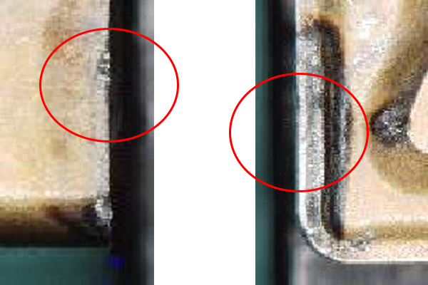
Examples of boundary wear
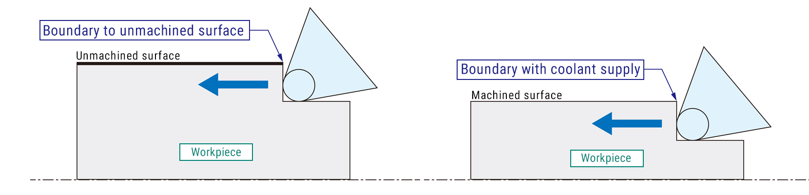
From left to right: “Boundary to unmachined surface”, “Boundary with coolant supply”
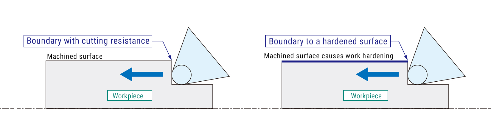
From left to right: “Boundary with cutting resistance”, “Boundary to a hardened surface”
When cutting distance increases and boundary wear progresses at an abnormally fast pace, the cutting edge becomes unusable, and the tool’s lifetime becomes extremely short. That is why it is important to avoid boundary wear when cutting hard material such as stainless steel or heat-treated material susceptible to work hardening.
There are 2 ways to avoid boundary wear: 1) By reducing load on cutting edge, and 2) By changing contact positions of cutting edge to workpiece surface.
1) By reducing load on cutting edge
A) By widening lateral cutting edge angle: Use a cutting tool with a wide lateral cutting edge angle. This will extend the length of cutting edge that removes material from a workpiece and reduce the thickness of cuttings chips generated. As a result, cutting force on certain distance becomes smaller, and you can suppress boundary wear. It should be noted, however, that this method may affect dimension accuracy of a thin, long, and low rigidity workpiece due to cutting resistance (thrust force) acting to bend the workpiece.

Information provided by Mitsubishi Materials Corporation
2) By changing contact positions of cutting edge to workpiece surface
A) By changing cutting depth of each cutting path: Changing cutting depth of each path means changing contact positions of main cutting edge to workpiece surface. In this way, boundary wear will be distributed instead of concentrating on one single spot.
B) By switching between taper and linear cutting: Similar to A) above, switching between taper and linear cutting means changing contact positions of main cutting edge to workpiece surface. In this way, boundary wear will be distributed instead of concentrating on one single spot
C) By changing feed rate per revolution of each cutting path: This approach is similar to A) and B) above and has an effect to suppress boundary wear of sub cutting edge. By changing contact positions of sub cutting edge to workpiece surface, boundary wear of sub cutting edge will be reduced.
D) By switching between push and pull machining: In turning operation, a cutting tool usually moves toward chuck. We call this as “push machining”. It is also possible to move a cutting tool toward tailstock, which is called “pull machining”. By switching between push and pull machining, both cutting edges alongside the diameter of a corner will be evenly used to cut a workpiece. In this way, boundary wear becomes less than repeating push machining only.
As the above example shows, some cutting tools are capable of both push and pull machining. Switching between push and pull machining contributes to shorter cycle time than repeated push machining, as the time spent for air cutting becomes less.

Information provided by Sandvik K.K.
These are some easy tips to reduce boundary wear. DMG MORI has many more ideas for you to avoid boundary wear. Please feel free to contact us.